General Overview – In SRHP, Sikidiri two nos. of Hydel units having capacity 65 MW each and both the units are in series (water discharged from 1st Unit is utilized for power generation by 2nd Unit).
Name of project – Subernarekha Hydel Project, Sikidiri
Dam – Getalsud Dam
- Type – Composite Type Earth Dam
- Catchment Area – 717 Km2
- Maximum height of dam – 118 ft. above river bed.
- Capacity (Full reservoir level)(FRL) – 1936 ft. equivalent to 2,34,000 Acre ft.
- Live storage (FRL–MDDL) - 1,87,000 Acre feet.
- Minimum draw down level (MDDL) - 1900 ft.
- Area of submerge at FRL – 8,600 Acres
- Date of commissioning – 1972
- Share of water (water supply) – 75 cusecs
- Share of water (Power Generation) – 275 cusecs
- TISCO (Tata) – 125 cusecs in Dry season
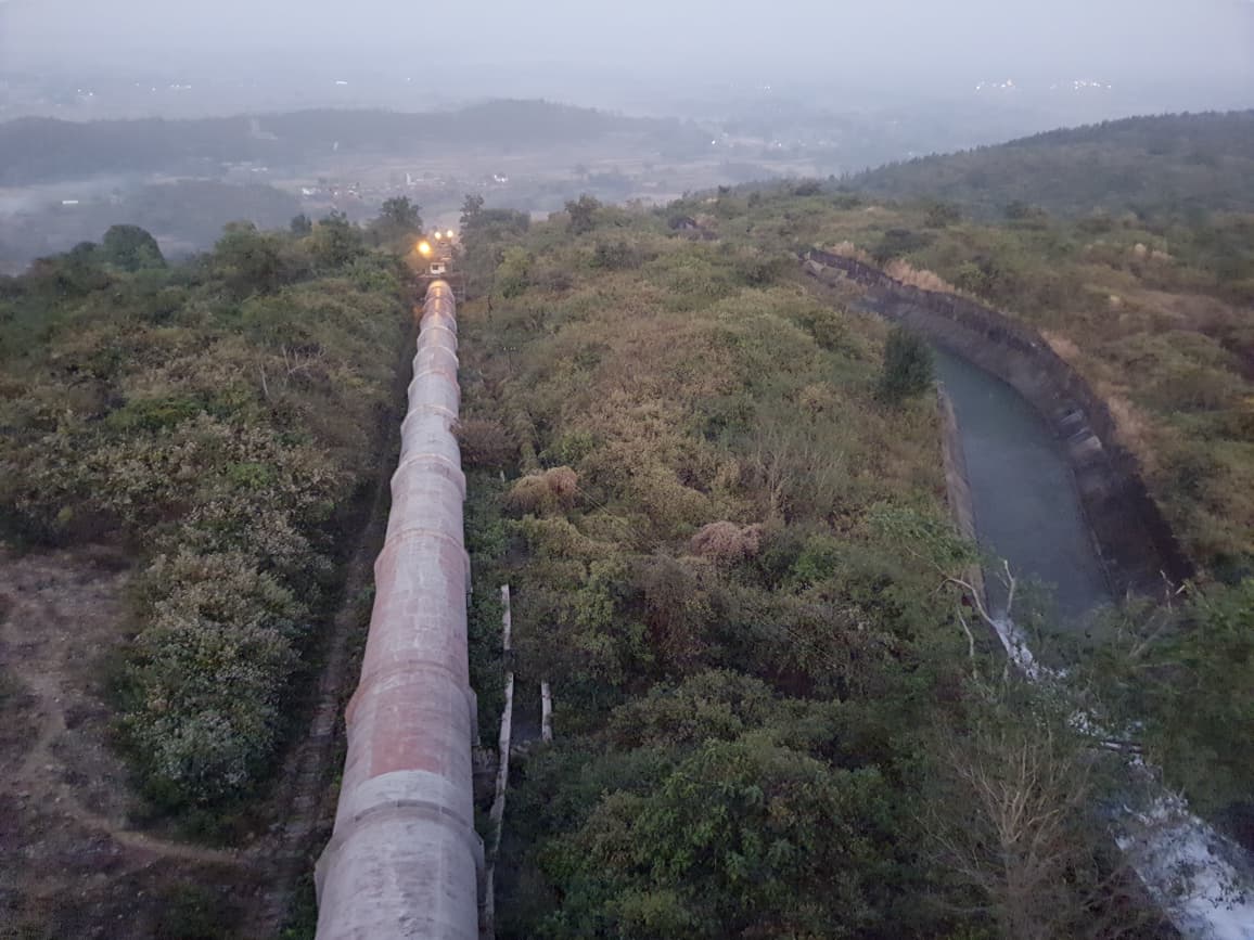
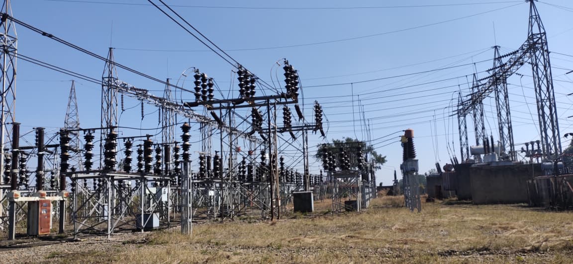
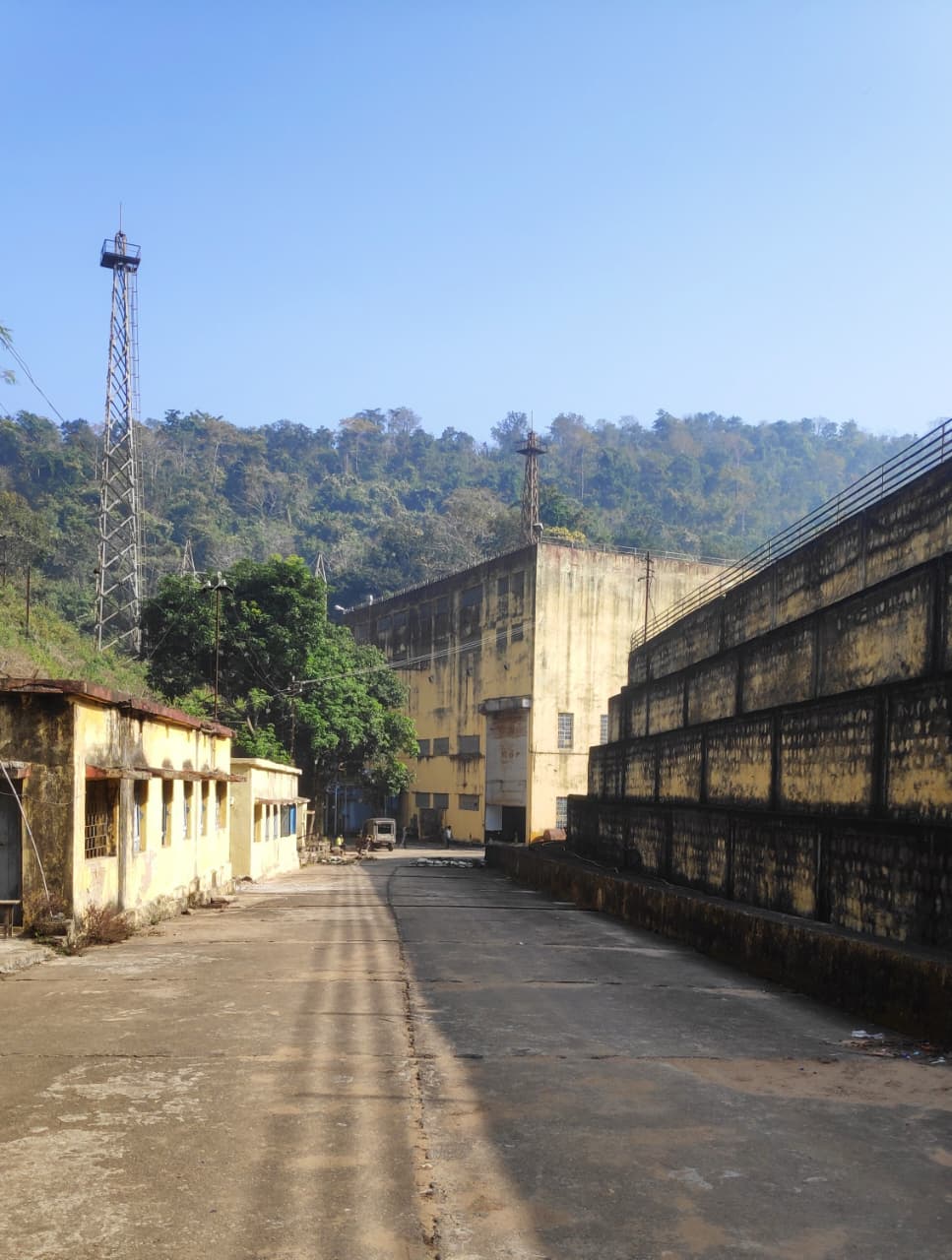
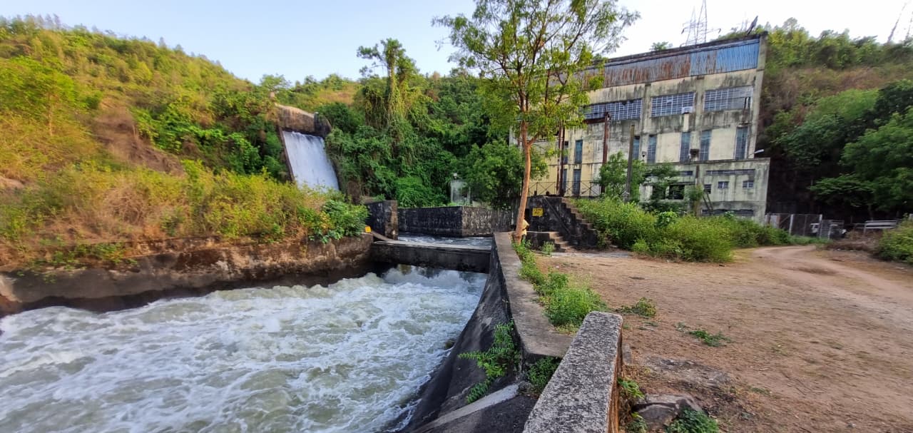
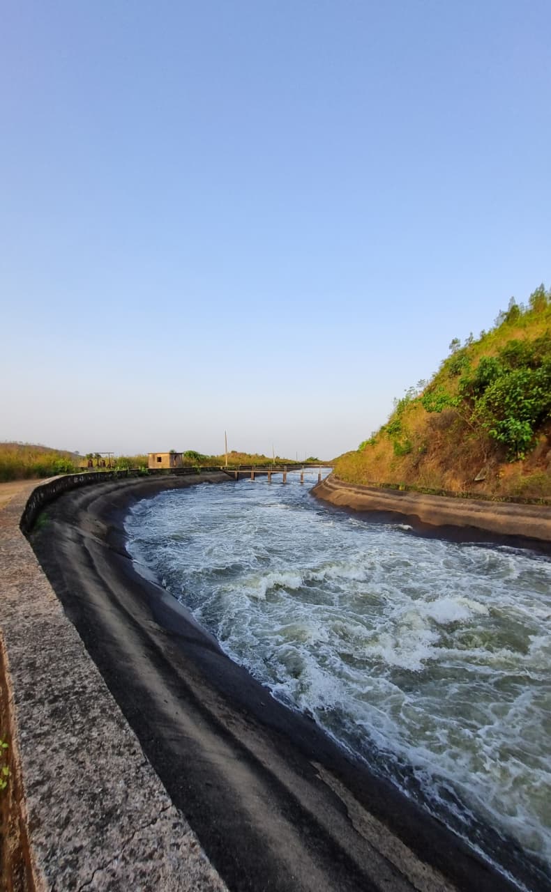
Scope of project – Following is the scope of project :-
- I. To supply 75 cusecs firm water to industrial belt of Ranchi including Ranchi city.
- II. To generate hydro electric power to the extent of 130 MW at 14% load factor for peaking Purposes for 3.4 hrs.
- III. To supply water to Tata and other industrial lower down.
- Shape – Trapezoidal
- Design Discharge – 2,000 cusecs
- Length of channel – 24,100 ft. (7348 meters or 7.348 km)
- Bed width – 15 ft.
- Shape – Trapezoidal
- Design Discharge – 2,000 cusecs
- Length of channel – 12,380 ft. (3,777 meters or 3.777 km)
- Bed width – 08 ft.
- Type – High Tensile Steel Pipe
- Diameter – 3.912 meters
- Length – 481.291 meters
Penstock No. 2 –
- Type – High Tensile Steel Pipe
- Diameter – 3.912 meters
- Length – 307.660 meters
Tunnel 1 –
- Type – D shape
- Length of tunnel – 1140 meters
- Depth – 18.37 ft. (D shape section)
Tunnel 2 –
- Type – D shape
- Length of tunnel – 366 meters
- Depth – 18.37 ft. (D shape section)
Hydro Turbine –
- Type of turbine – Francis with vertical shaft. (RA-170/638 –BVM-2800)
- Runner diameter – 2800 mm
- Speed of rotation – 300 r.p.m.
- Normal output – 65 MW + 10% overload
- No. of guide vanes – 24
- No. of stay vanes – 12
- No. of runner blades -16
Governing system of turbine –
- Type of governor – EHG-40
- Operating duty of Governor – Peak Load / Frequently Control
- Diameter of Main guide valve – 100 mm
- Diameter of Main guide valve – 100 mm
- Normal operating of oil pressure – 40 Kg/cm2
- Diameter of valve – 2600 mm
- Static head – 140 m
- Max. Discharge – 61 M3/Sec.
- Type of product – S.V. 570/170 – 20
- Type of generator – Suspension
- Rated output – 72000 KVA, 65 MW + 10% overhead
- Rated voltage – 11 KV
- Rated current – 3780 Amps.
- Rated power factor (Lagging) – 0.9
Machine Specifications
Machine Excitation – Conventional
- Main Exciter:
- Type: SE-139/22 – BP
- Rated Capacity: 240 kW / 620 kW
- Rated Voltage: 210 V / 340 V
- Pilot Exciter:
- Type: SE-72/10 – 10 P
- Rated Capacity: 8 kW
- Rated R.P.M.: 300
Stator
- Height: 3150 mm
- Diameter of Air Gap: 4900 mm
- Outside Diameter of Frame: 7100 mm
- Weight of Wound Stator: 121 T
- Number of Sectors: 3
- Class of Insulation: B
- Total Generator Weight: 415 T
- Weight of Rotor: 193 T
Cooling Systems
- Lower Guide Bearing Oil Cooler:
- Cooling water flow: 3.75 m³/hr
- Max. Temp. of cooling water at inlet: 35°C
- Upper Guide Bearing Oil Cooler:
- Cooling water flow: 11.35 m³/hr
- Allowable working pressure: 2.5 kg/cm²
- Testing water pressure during 1 hr: 3.5 kg/cm²
- Thrust Bearing Oil Cooler:
- Cooling water flow: 43 m³/hr
- Allowable working pressure: 3 kg/cm²
- Testing water pressure during 30 minutes: 4 kg/cm²
- Turbine Guide Bearing:
- Cooling water flow: 2.00 m³/hr
- Max. Temp. of cooling water at inlet: 35°C
- Air Cooler:
- Air flow: 4 m³/sec
- Cooling water flow: 37 m³/hr
- Allowable working water pressure: 3 kg/cm²
Brief
- Installed capacity: 65 MW each
- Year of commissioning:
- Unit No. 1: 1977
- Unit No. 2: 1980
- Discharge: 2000 cusec for full load
- Plant Load Factor: 14% — plant should run daily for 03h 21m 36s (1225 hrs/year as per water availability)
- Turbine: Francis with vertical shaft
- Peak draft (Discharge): 2000 cusec
- Firm draft (No load discharge): 300 cusec
- Gross head: 133 m
- RPM: 300
- Rated output: 72,000 kVA
- Rated voltage: 11 KV
- Type of governor: EHG 40
- Type of generator: Suspension
- Generation (2023–24):
- Unit No. 1: 49.408 MU
- Unit No. 2: 47.425 MU
- Total: 96.833 MU
- Present status: Both units available for generation
Water Availability
- Reservoir level: 1924.20 ft as on 10-04-2024
- Radial gates open at: 1934.00 ft
- Water requirement per hour: 2000 cusec (165 Acre-ft/hr)
Short Term Planning / Annual Maintenance
Mechanical Works
- Unit No. 1:
- Centering, leveling, alignment of turbine
- Testing/rectification of defects in turbine bearings
- Testing/rectification of defects in all coolers, air, water & oil pipelines and valves
- Ultrasound testing of penstock
- Scheduled repair and maintenance of mechanical parts/equipment as required
- Unit No. 2:
- Scheduled repair and maintenance of mechanical parts/equipment as required
- Replacement of spider pipes, overhauling of brake and jack system
- Testing/rectification of defects in all coolers, air, water & oil pipelines and valves
- Ultrasound testing of penstock
Civil Works
- Total area: ~485 Acres (includes power canal, power house I & II, switchyard, store, road, residential colony, I.B.)
- Residential quarters: ~200
- Repair/maintenance of power canal, switchyard building, power houses 1 & 2, office building, residential quarters, etc.
- Comprehensive repair of canal structures (PC-I to IV) after severe damage observed during complete dry out; urgent to prevent accidents and leakage
Renovation and Modernisation
Units are operational after ~45 years since commissioning (total generation: 7486 MU). However, equipment and technology are obsolete, requiring R&M to address frequent glitches.
Mechanical
- Upgradation of old runner, labyrinth, pivot ring, stay ring
- New guide vanes with self-lubricating bushings
- Dynamic oil cooling for guide and thrust bearings
- Upgrade brake and jacking system
- Upgraded cooling system for bearing coolers and stator winding coolers
- Upgrade MIV sealing and operating system
- Modernize water intake/outlet gates and operation system
- Upgrade OPU arrangement with automation
- Automate all important valves
- Collapsible gate in tail race in place of permanent barrier
- Upgrade governing system with servo system
- Rehabilitate penstock and associated systems
Electrical
- Static excitation system
- Rehabilitate with class F insulation (replace class B) for stator winding
- Replace static relay system with Micom or equivalent
- Auxiliary power from 11 KV generation output
- Auto synchronization system
- Replace old 80 MVA GT transformer with new (updated protection & cooling)
Note: Above works are based on current site engineer assessment; expert consultancy may be required for detailed DPR preparation.
Operational Statistics (as on 31-03-2024)
Progressive Running Hours (since commissioning)
- PH-I: 63,577:10 hrs
- PH-II: 70,658:33 hrs
Cumulative Generation (since commissioning)
- PH-I: 3748 MU
- PH-II: 3738 MU
- Total: 7486 MU
Main Heads / Points – RLA Study
Hydro Turbine
- The current turbine has been in continuous operation since commissioning.
- Assessment of aging effects on turbine materials is required to determine residual life expectancy and suggest alternatives.
- Possible upgrades: old runner, guide vanes, related brake and jacking system, draft tube, etc.
Hydro Generator
- Includes stator winding, stator core, rotor & other components, and excitation system.
- Currently using Class ‘B’ insulation for stator winding; should be upgraded to Class ‘F’ insulation for:
- Higher allowable working temperature
- Better thermal conductivity
- Improved dielectric properties
Generator Transformer
- Replace existing old 80 MVA GT transformer with a higher rating and updated protection & cooling arrangement.
- Assessment to be made regarding uprating this system.
Governor
- Currently installed: G-40 series electro-hydraulic governor (EHG) [BHEL make].
- Issues: unable to operate units in auto mode; system is obsolete (since commissioning).
- RLA should assess requirement for an upgraded governor compatible with the latest technology, SCADA system, or alternatives.
Pipelines and Waterways
Penstock
- In service since commissioning; visible wear and tear.
- Frequent welding required due to occurrence of holes.
- Rusted iron chips found during annual maintenance (suggesting thickness reduction).
- Ultrasonic testing required to assess remaining life.
Canals / Bye-pass / Tunnels
- Condition is poor; only makeshift R&M work being done (pot-hole filling, parapet wall repairs, panel repairs).
- Complete assessment desired from Getalsud dam to PH-II, including:
- Power Canals I to IV
- Cross drains of Power Canal I & II
- Escape channels I & II (velocity breakers damaged, water leakage)
- Bye-pass
- Tunnels I & II (damaged ceiling portions)
- Tail race
Additional Information (CMS-Managed)
Project Overview
brief
- Installed capacity: 65 MW each
- Unit No. 1 Commissioning: 1977
- Unit No. 2 Commissioning: 2025
- Discharge: 3000 cusec for full load
- Plant Load Factor: 14% — plant should run daily for 03h 21m 36s (1225 hrs/year as per water availability)
- Turbine: Francis with vertical shaft
- Peak draft (Discharge): 2000 cusec
- Firm draft (No load discharge): 300 cusec
- Gross head: 233 m
- RPM: 300
- Rated output: 72,000 kVA
- Rated voltage: 11 KV
- Type of governor: EHG 40
- Type of generator: Suspension
- Unit No. 1 Generation (2023–24): 49.408 MU
- Unit No. 2 Generation (2023–24): 47.425 MU
- Total Generation (2023–24): 96.833 MU
- Present status: Both units available for generation
scope
- I: To supply 75 cusecs firm water to industrial belt of Ranchi including Ranchi city.
- II: To generate hydro electric power to the extent of 130 MW at 14% load factor for peaking Purposes for 3.4 hrs.
- III: To supply water to Tata and other industrial lower down.
water availability
- Reservoir level: 1924.20 ft as on 10-04-2024
- Radial gates open at: 1934.00 ft
- Water requirement per hour: 2000 cusec (165 Acre-ft/hr)
Technical Specifications (Database)
cooling air
- Air flow (m³/sec): 4
- Cooling water flow (m³/hr): 37
- Allowable working water pressure (kg/cm²): 3
cooling lower guide
- Cooling water flow (m³/hr): 3.75
- Max. Temp. of cooling water at inlet: 45°C
cooling thrust
- Cooling water flow (m³/hr): 43
- Allowable working pressure (kg/cm²): 3
- Testing water pressure during 30 minutes (kg/cm²): 4
cooling turbine guide
- Cooling water flow (m³/hr): 2.00
- Max. Temp. of cooling water at inlet: 35°C
cooling upper guide
- Cooling water flow (m³/hr): 11.35
- Allowable working pressure (kg/cm²): 2.5
- Testing water pressure during 1 hr (kg/cm²): 3.5
dam
- Type: Composite Type Earth Dam
- Catchment Area (Km²): 771
- Maximum height of dam: 218 ft. above river bed
- Capacity (Full reservoir level)(FRL): 1936 ft. equivalent to 2,34,000 Acre ft.
- Live storage (FRL–MDDL): 1,87,000 Acre feet
- Minimum draw down level (MDDL): 1900 ft
- Area of submerge at FRL: 8,600 Acres
- Date of commissioning: 1972
- Share of water (water supply) (cusecs): 75
- Share of water (Power Generation) (cusecs): 275
- TISCO (Tata): 125 cusecs in Dry season
disc valve
- Diameter of valve (mm): 2600
- Static head (m): 140
- Max. Discharge (M³/Sec.): 61
excitation main
- Type: SE-139/22 – BP
- Rated Capacity: 240 kW / 620 kW
- Rated Voltage: 210 V / 340 V
excitation pilot
- Type: SE-72/10 – 10 P
- Rated Capacity (kW): 8
- Rated R.P.M.: 300
generator
- Type of product: S.V. 570/170 – 20
- Type of generator: Suspension
- Rated output: 72000 KVA, 65 MW + 10% overhead
- Rated voltage (KV): 11
- Rated current (Amps.): 3780
- Rated power factor (Lagging): 0.9
governing system
- Type of governor: EHG-40
- Operating duty of Governor: Peak Load / Frequently Control
- Diameter of Main guide valve (mm): 100
- Normal operating of oil pressure (Kg/cm²): 40
penstock 1
- Type: High Tensile Steel Pipe
- Diameter (meters): 3.912
- Length (meters): 481.291
penstock 2
- Type: High Tensile Steel Pipe
- Diameter (meters): 3.912
- Length (meters): 307.660
power channel 1
- Shape: Trapezoidal
- Design Discharge Power Channel (cusecs): 2,000
- Length of channel: 24,100 ft. (7348 meters or 7.348 km)
- Bed width (ft.): 15
power channel 2
- Shape: Trapezoidal
- Design Discharge (cusecs): 2,000
- Length of channel: 12,380 ft. (3,777 meters or 3.777 km)
- Bed width (ft.): 08
stator
- Height (mm): 3150
- Diameter of Air Gap (mm): 4900
- Outside Diameter of Frame (mm): 7100
- Weight of Wound Stator (T): 121
- Number of Sectors: 3
- Class of Insulation: B
- Total Generator Weight (T): 415
- Weight of Rotor (T): 193
tunnel 1
- Type: D shape
- Length of tunnel (meters): 1140
- Depth: 18.37 ft. (D shape section)
tunnel 2
- Type: D shape
- Length of tunnel (meters): 466
- Depth: 18.37 ft. (D shape section)
turbine
- Type of turbine: Francis with vertical shaft. (RA-170/638 –BVM-2800)
- Runner diameter (mm): 2800
- Speed of rotation (r.p.m.): 300
- Normal output: 65 MW + 10% overload
- No. of guide vanes: 24
- No. of stay vanes: 12
- No. of runner blades: 16
Maintenance Items
civil
- Total area: ~485 Acres (includes power canal, power house I & II, switchyard, store, road, residential colony, I.B.)
- Residential quarters: ~200
- : Repair/maintenance of power canal, switchyard building, power houses 1 & 2, office building, residential quarters, etc.
- : Comprehensive repair of canal structures (PC-I to IV) after severe damage observed during complete dry out; urgent to prevent accidents and leakage
mechanical unit1
- : Centering, leveling, alignment of turbine
- : Testing/rectification of defects in turbine bearings
- : Testing/rectification of defects in all coolers, air, water & oil pipelines and valves
- : Ultrasound testing of penstock
- : Scheduled repair and maintenance of mechanical parts/equipment as required
mechanical unit2
- : Scheduled repair and maintenance of mechanical parts/equipment as required
- : Replacement of spider pipes, overhauling of brake and jack system
- : Testing/rectification of defects in all coolers, air, water & oil pipelines and valves
- : Ultrasound testing of penstock
rla canals
- : Condition is poor; only makeshift R&M work being done (pot-hole filling, parapet wall repairs, panel repairs).
- : Complete assessment desired from Getalsud dam to PH-II, including: Power Canals I to IV, Cross drains of Power Canal I & II, Escape channels I & II (velocity breakers damaged, water leakage), Bye-pass, Tunnels I & II (damaged ceiling portions), Tail race
rla generator
- : Includes stator winding, stator core, rotor & other components, and excitation system.
- : Currently using Class 'B' insulation for stator winding; should be upgraded to Class 'F' insulation for: Higher allowable working temperature, Better thermal conductivity, Improved dielectric properties
rla governor
- : Currently installed: G-40 series electro-hydraulic governor (EHG) [BHEL make].
- : Issues: unable to operate units in auto mode; system is obsolete (since commissioning).
- : RLA should assess requirement for an upgraded governor compatible with the latest technology, SCADA system, or alternatives.
rla penstock
- : In service since commissioning; visible wear and tear.
- : Frequent welding required due to occurrence of holes.
- : Rusted iron chips found during annual maintenance (suggesting thickness reduction).
- : Ultrasonic testing required to assess remaining life.
rla transformer
- : Replace existing old 80 MVA GT transformer with a higher rating and updated protection & cooling arrangement.
- : Assessment to be made regarding uprating this system.
rla turbine
- : The current turbine has been in continuous operation since commissioning.
- : Assessment of aging effects on turbine materials is required to determine residual life expectancy and suggest alternatives.
- : Possible upgrades: old runner, guide vanes, related brake and jacking system, draft tube, etc.
rm electrical
- : Static excitation system
- : Rehabilitate with class F insulation (replace class B) for stator winding
- : Replace static relay system with Micom or equivalent
- : Auxiliary power from 11 KV generation output
- : Auto synchronization system
- : Replace old 80 MVA GT transformer with new (updated protection & cooling)
rm mechanical
- : Upgradation of old runner, labyrinth, pivot ring, stay ring
- : New guide vanes with self-lubricating bushings
- : Dynamic oil cooling for guide and thrust bearings
- : Upgrade brake and jacking system
- : Upgraded cooling system for bearing coolers and stator winding coolers
- : Upgrade MIV sealing and operating system
- : Modernize water intake/outlet gates and operation system
- : Upgrade OPU arrangement with automation
- : Automate all important valves
- : Collapsible gate in tail race in place of permanent barrier
- : Upgrade governing system with servo system
- : Rehabilitate penstock and associated systems
Operational Statistics
generation
- PH-I: 3748
- PH-II: 3738
- Total: 7486
running hours
- PH-I: 63,577:10
- PH-II: 70,658:33
